Stereo Audio DSP Speaker

A custom STM32 board that filters music in real time, from 3.5mm jack to speaker

In progress · Electronics final project with Tane
Back to Engineering Projects View on GitHub

Project Overview

Tane and I are designing a stereo audio DSP board from scratch for our Electronics final project. A phone or laptop plugs into a 3.5mm jack, the audio is digitized by a 24-bit ADC, filtered on an STM32 in real time, converted back to analog, and amplified to drive a small speaker.

We set ourselves one rule: no dev boards. No Arduino, Raspberry Pi, or ESP. The microcontroller, converters, and amplifier all sit on our own PCB. My focus is circuit design and PCB design and fabrication; Tane leads the DSP and filter design.
Signal Chain

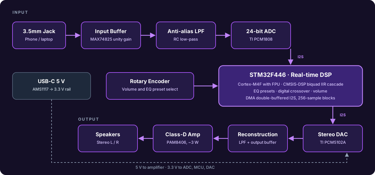
Audio enters through a unity-gain op-amp buffer so a phone's output can drive the ADC cleanly, then passes an anti-alias low-pass filter. After the STM32 processes it, the DAC output goes through a reconstruction filter and output buffer before the class-D amplifier.

Block diagram of the speaker signal chain from 3.5mm input through ADC, STM32 DSP, DAC, and class-D amplifier
System block diagram

Schematic

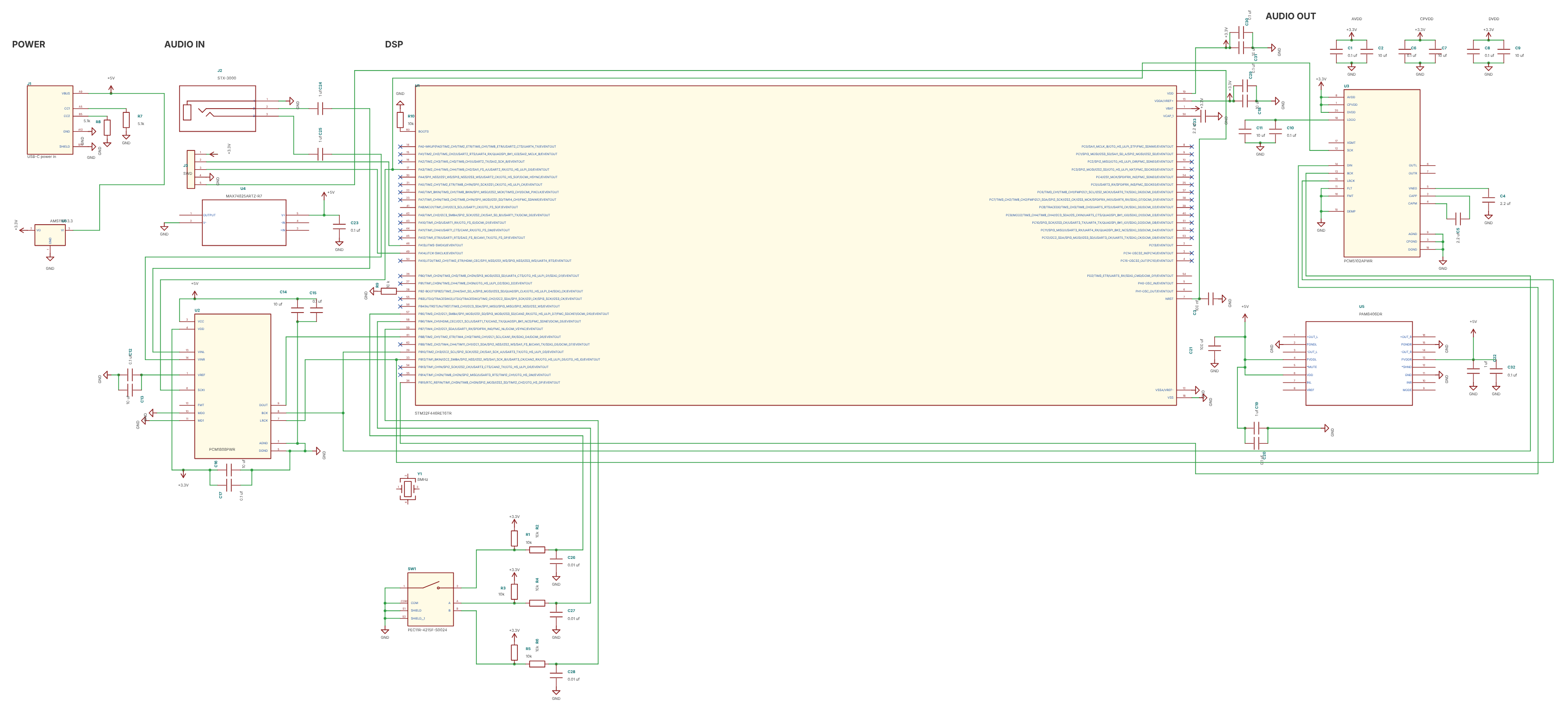
The full schematic is captured in KiCad 10, organized into power, audio in, DSP, and audio out sections. We built a custom symbol and footprint library for the STM32F446, PCM1808, PCM5102A, MAX74825, PAM8406, the audio jack, and the rotary encoder, with 3D models for each.

KiCad schematic of the speaker DSP board
KiCad schematic (work in progress). Open full size

Key Components

FunctionPartWhy
MicrocontrollerSTM32F446RET6Cortex-M4 with a hardware FPU and I2S/SAI peripherals for real-time filtering
Stereo ADCTI PCM180824-bit audio input over I2S
Stereo DACTI PCM5102ALine-level analog output over I2S
Op-ampsADI MAX74825Rail-to-rail input/output buffers and filters
AmplifierPAM8406Class-D, around 3 W for a small speaker
PowerUSB-C 5 V + AMS1117-3.35 V for the amp, 3.3 V rail for logic and converters
ControlsPEC11R rotary encoderVolume and EQ preset selection

DSP Firmware

Filtering runs as a cascade of biquad IIR filters using ST's CMSIS-DSP library. Each stage computes

y[n] = b0·x[n] + b1·x[n-1] + b2·x[n-2] - a1·y[n-1] - a2·y[n-2]

so changing the EQ curve or crossover frequency only means swapping coefficients, which we design and verify in MATLAB first.

  • EQ presets: flat, low/high shelf, notch
  • Digital 2-way crossover (stretch goal)
  • Volume scaling before the DAC

Audio moves by DMA into a double buffer. Half-complete and complete interrupts each process one 256-sample block while the other half fills.

void HAL_I2S_RxHalfCpltCallback(I2S_HandleTypeDef *hi2s)
{
    process_audio_block(&dma_buffer[0]);
}

void HAL_I2S_RxCpltCallback(I2S_HandleTypeDef *hi2s)
{
    process_audio_block(&dma_buffer[AUDIO_BLOCK_SIZE]);
}

Next Steps

  • Finish the schematic: decoupling, status LEDs, SWD programming header, speaker connectors
  • Lay out the PCB and send it out for fabrication
  • Bring-up: blink an LED, then pass audio straight through, then enable filtering
  • Stretch goals: rechargeable LiPo with USB-C charging, OLED for volume and preset